The quality of an aerospace induction-brazed joint depends on controlling the complete joining process rather than simply melting the filler metal. Joint clearance, surface condition, filler compatibility, heating uniformity, coil design, atmosphere, fixturing, and thermal history all influence the final result. This is particularly important in aerospace manufacturing, where a joint that appears acceptable from the outside may still contain incomplete wetting, internal voids, or local thermal damage.
Why Is Joint Clearance Critical in Induction Brazing?
Brazing depends on capillary action to draw molten filler metal through the joint interface. The gap must therefore be large enough to permit filler flow but controlled enough to maintain effective capillary action.
An excessively narrow clearance can restrict filler movement, while an overly wide gap may reduce capillary performance and create regions with incomplete filling.
Clearance also changes during heating. Different materials and component geometries expand at different rates, so the gap measured at room temperature may not represent the effective clearance at brazing temperature.
A controlled induction brazing process consequently begins with joint design rather than with the induction machine itself.
In aerospace assemblies involving dissimilar materials, this thermal-expansion effect should be reviewed carefully during process development.
How Does Surface Preparation Affect Joint Integrity?
Brazing filler needs clean surfaces to wet and flow correctly. Oil, machining fluid, fingerprints, oxide films, abrasive residue, or contamination remaining from previous production stages can interfere with wetting.
Surface preparation should therefore be treated as a controlled production step. The cleaning method needs to be suitable for the base metals and should not leave chemical residues that become problematic during heating.
Storage conditions after cleaning also matter. Components that remain exposed to an uncontrolled atmosphere for a long period may begin oxidizing again before they enter the brazing station.
In demanding aerospace production, repeatable surface preparation is often just as important as repeatable heating.
Why Must Both Components Reach the Correct Temperature?
Induction heating does not automatically heat every part of an assembly at the same rate.
Differences in thickness, material, geometry, mass, and electromagnetic response can cause one component to reach brazing temperature before the other. The filler metal may then melt against the hotter surface even though the second surface is not yet hot enough for reliable wetting.
For manufacturers using induction heating for aerospace industry, temperature balance across the joint should therefore be verified during process development.
A single temperature measurement taken from the hottest accessible location may not represent the condition inside the joint.
How Does Coil Design Influence Joint Quality?
The induction coil determines where electromagnetic energy is concentrated. Its geometry should direct heat toward the joint while minimizing unnecessary thermal exposure of surrounding features.
Understanding the induction coil working principle helps explain why coil shape and position can have such a large effect on brazing consistency.
A thick fitting joined to a thin tube, for example, may require more energy to be concentrated toward the fitting because its greater thermal mass causes it to heat more slowly.
Coil-to-part distance is also important. If the fixture does not locate each component consistently, electromagnetic coupling can change from one cycle to the next.
How Should Filler Metal Be Selected?
The filler alloy needs to be metallurgically compatible with the base materials and appropriate for the intended service conditions.
Its melting range should provide a practical process window. If the brazing temperature is too close to a temperature at which the parent material loses desirable properties or suffers excessive metallurgical change, process control becomes more demanding.
Filler quantity should also be controlled. Excess filler does not compensate for an unsuitable joint gap or poor wetting. Instead, it may create uncontrolled external fillets or obscure indications of incomplete internal flow.
The objective is to use enough filler to complete the designed joint without relying on excessive material.
How Do Atmosphere and Oxidation Affect Brazing?
Oxidation can interfere directly with filler wetting.
Depending on the alloys involved, the process may use flux, inert gas, a reducing atmosphere, or vacuum conditions. The correct approach depends on the base material, filler alloy, joint design, and applicable aerospace production requirements.
Heating time also affects oxidation. Even when the maximum temperature is technically correct, unnecessarily long exposure at elevated temperature can increase surface reaction and metallurgical interaction.
For this reason, the brazing cycle should reach the appropriate joint temperature efficiently, allow complete filler flow, and then move into controlled cooling.
What Defects Indicate an Unstable Brazing Process?
| Joint Condition | Likely Cause | Process Review |
|---|
| Incomplete fill | Poor clearance or uneven heating | Check joint gap and temperature balance |
| Internal voids | Contamination or interrupted filler flow | Review cleaning and thermal cycle |
| Local overheating | Excessive field concentration | Adjust coil position or power profile |
| Poor wetting | Oxidation or insufficient temperature | Review surface preparation and atmosphere |
| Distortion | Excessive heat input | Reduce unnecessary thermal exposure |
| Part-to-part variation | Inconsistent positioning | Improve fixture repeatability |
A process engineer should identify the physical cause of the defect before increasing machine power or extending heating time. Those changes may hide one problem while creating another.
What Should Be Controlled on the Brazing Machine?
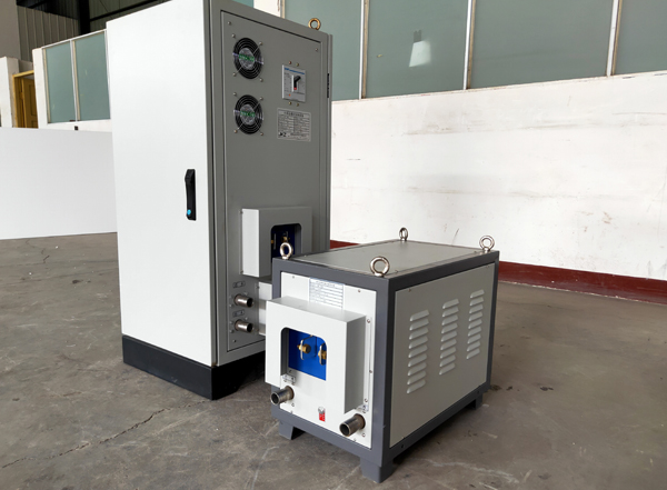
Production induction brazing equipment should allow the important cycle variables to be reproduced reliably.
Power, heating time, coil position, component location, temperature, and cooling conditions should remain within the qualified process window.
Coil condition also deserves attention. Physical deformation, scale accumulation, cooling problems, or damage can change electromagnetic performance even if the machine recipe remains unchanged.
For automated production, recipe control and fixture repeatability can significantly reduce operator-dependent variation.
How Should an Aerospace Brazing Process Be Validated?
Validation should use representative production components rather than idealized laboratory samples.
The process should be tested across realistic tolerances in joint clearance, component geometry, starting temperature, filler placement, and workpiece position.
Inspection requirements then depend on the component and applicable engineering specification. Visual examination alone may not be sufficient for joints where internal integrity is critical.
The important goal is to confirm that normal production variation remains inside a stable operating window.
Conclusion
Aerospace induction brazing quality is created by the interaction of joint design, material preparation, filler selection, controlled heating, atmosphere, and repeatable fixturing. The induction machine provides a precise heat source, but it cannot compensate for an unsuitable joint or inconsistent process preparation. The strongest production results come from treating the joint and heating system as one controlled manufacturing process.
FAQ
1. Why can a brazed joint look good but still fail inspection?
The external fillet does not always show whether filler metal completely flowed through the internal joint. Internal voids, poor wetting, or incomplete fill can remain hidden beneath an acceptable-looking surface.
2. Is higher induction power better for aerospace brazing?
Not necessarily. Excess power can create steep temperature differences or localized overheating. The priority should be uniform joint temperature within the required brazing window.
3. How can manufacturers improve brazing repeatability?
Consistent surface preparation, fixed joint clearance, repeatable workpiece positioning, controlled filler placement, stable coil geometry, and reproducible heating parameters are the main factors supporting consistent production.
 en
en  cn
cn  jp
jp  ko
ko  de
de  es
es  it
it  ru
ru  pt
pt  th
th  vi
vi  pl
pl 




 Call us on:
  Email Us:
  NO. 688th South Baoguang Road, Xindu District, Chengdu City, Sichuan Province, China